Lighting and Simplified Signalling - Year 1, 2021
The goal of this project is to use lighting in interesting ways to help with signaling while also promoting the attractiveness of the canal and the cities it was built on. Two methods were used, each using their own interesting materials that have gained a bit of traction in recent years.
The first method applies transparent concrete and railed lights underground. This method may use controls and sensors to indicate desired direction, desired speeds, and desired stops in a clear and concise method.
The second method applies bioluminescent lighting along the entirety of the canal with the goal of promoting tourism. This method may also apply methods to recycle byproducts using methods imitating biology in some fashion.
Design Specifics
-

Lighting
Lighting is an important tool for humans as our sight is one of our most basic functions. In an attempt to improve the signaling and overall attractiveness of the canal, or certain parts of the canal, this section analyzes the potential costs of extra lighting alongside its goals. The canal in its current state lacks appeal which likely has contributed to a decline in visitors despite the natural wonder in a nearby city. The plans below use special materials to create attractiveness while also providing the desired effects.
Plan A: Underground Lighting a.I: Light Transmission
With the advent of translucent concrete in the early twenty-first century, though theorized in the century prior, we have found a material that is both structurally sound yet can pass through light and resist heat. By applying this material at the base of the Welland Canal, we can potentially create lighting effects that appeal to the eyes while conveying information in its simplest forms. According to Anu Dhonchak’s summary of the material;
“Translucent concrete is a concrete based material with light-transmissive properties, obtained due to embedded light optical elements like optical fibres in it. Light is conducted through the stone from one end to the other. This results in a certain light pattern on the other surface, depending on the fibre structure. Optical fibres transmit light so effectively that there is virtually no loss of light conducted through the fibres” 1a(Dhonchak).
The optical fibres within the concrete, according to Baofeng Huang of the Nanjing Tech University, the ratio of light transmission correlates to the bending radius of the optical fibres within the finished concrete product 2a(Huang and Cacciola). As seen in the diagram that their report provided, shown to the right, the maximum light transmission ratio through the optical fibres is just about 96% (the “Straight OF” line). As the bending radius reduces and the curve of the optical fibre increases, less light can pass through. Despite this, for the most part, the light transmission remains above 95%.
Of course there isn’t only concrete above the base of the canal as ten metres of water flow overtop. The website for Exploring Our Fluid Earth 3a(Seraphin et al.) lists the effects of light as it passes through water. To summarize, water is almost completely opaque to most of the electromagnetic spectrum, the only exception being the visible light spectrum. Because visible light contains a varied range of wavelengths, water also blocks out more red and green light than blue light, causing the ocean’s blue appearance. To find the true light transmission ratio for the plan, we have to consider each of these colours.
-

Lighting Depth and Surface Light
The graph above displays an altered version of the graph that appears on the mentioned website. According to Britannica, the minimum depth of the canal is nine metres with an average of just under ten metres 4a(Guar et al.). To better display the effects of water on light, a line was extended down from ten metres for each. Blue light, according to the diagram, retains about 70% of its light. Green retains less than half while red is left with just over a quarter. The blue square just below shows what white light would become at just under ten metres of water. For simplicity, I analyzed the intensity of blue light that passes through. We can find this by taking the product of both ratios and applying it to a base intensity of light, which I chose to be 1000 lumens. These calculation resulted in just under 1500 lumens passing through both the water and the concrete (at a safer 95% ratio) showing as the base 1000 lumens above the water, which of course is further dimmed by the air and, if applicable, the square-cube law as it spreads.
a.II: Applications and Costs)
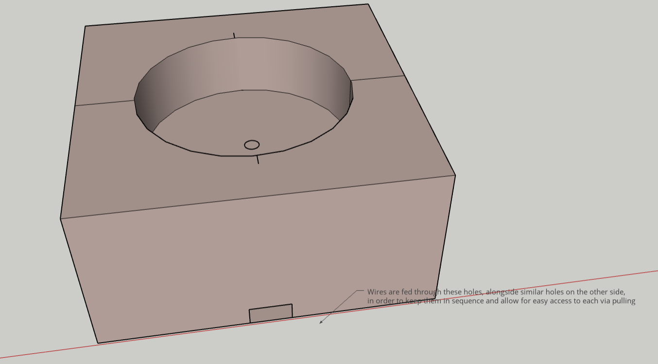
The linked example 5a is a store page for a standard 1500 lumen LED, which I will be using as an example for these calculations. The general idea for these lights are for signalling at bridges and locks. This is to prevent ship-to-ship and ship-to-bridge collisions such as the one which rendered the bridge near Port Robinson unusable. Rooms should be excavated along the side of the canal near these locks and bridges where the LEDs may be slid through, likely atop a rail above some backup grating. As a side note, it would be ideal to use a custom container for these lights for ease of access where pulling at the nearest container also pulled along the rest of the containers.
-

LED Lights Under Water
The example image to the right displays how these lights slide underneath the canal. The perpendicular lights all flash together to indicate a stop (ideally alongside current signage) to quickly and easily convey the intended message. When a ship is allowed to enter, the parallel or diagonal lights flash in sequence towards the entrance of the lock. The diagonal lights may also flash the other direction if wanted for outgoing ships. Both rails may be connected to a separate or already-standing control. To account for traffic in the other direction, this would then be replicated on the other side of the lock. Bridges would utilize a similar system of lights, but may instead have two rooms each with their own set of perpendicular and either parallel or diagonal lights. This would then be replicated along the other side of the bridge for traffic in the other direction.
The Canadian Encyclopedia describes the width of the canal to be just over 94 metres 6a(Gayler and Jackson). As this is relatively thin compared to the length of the canal, the number of lights underneath is generally arbitrary. To use the image above as an example, let’s say we use five 1500 lumen LEDs diagonally and seven perpendicularly. That is a total of twenty-four LEDs and a maximum of eight on at any time. Using a minimum of $12 and a maximum of $15 per LED (based on this product 5a(Amazon, 28 Nov 2021), we can find that the total LED cost results in a $288 to $360 price for the LEDs. The example LED has a 14 Watt usage, so the maximum usage at any point would be 112 Watts or 0.112 kWh. Using a $0.130 per kWh price point for Ontario 7a(Urban), we can see that it takes about $0.015 to run these lights for an hour. This is equivalent to $92.16 a year assuming the use of 1500 lumen LEDs day and night. The translucent concrete, being a newer production, may be more expensive. An article by the Journal of Commerce in 2013 lists an estimated price of $2,700 per square meter 10a(Moneo).
-

Costs Associated with the Project
Ia.III: Length-Spanning Underground Lights)
Although less useful for signalling, one might lean towards the use of these lights for tourism and attraction by spanning them across the canal. This, of course, would require much more excavation and interfere with zoning unless the rails these lights sit upon are very long. The graph to the right portrays the number of lights versus the distance between the lights by a red line over the canal’s 44000 metre length 4a(Guar et al.). The blue zone above it is the price range, using the same LED example as before. The x-axis is the shared distance between the lights.
The point at the centre of the curve, where decreasing the distance between lights would increase the cost exponentially more and increasing the distance decreasing the cost exponentially less, would be considered an ideal distance from a pricing-to-light-density standpoint. The value at that centrepoint happens to be just under 211 LEDs throughout the canal, which I rounded down to 210. The distance between those lights, as the curve is symmetrical, is just over 211 metres after the rounding. The price range for this value of LEDs solves to a range of $2,520 to $3,150. The Watt usage solves to 2.94 kW which costs $3,302.21 a year in electricity assuming all lights are on, all the time.
A quick search on Wikipedia shows that the largest ship that can cross the canal has a length of 225.6 metres 8a(Wikipedia). Conveniently, this value is very close to our ideal centrepoint which further supports the use of that value. For an example of a company that uses translucent concrete, see Germany’s Lucem 9a(Lucem). Lastly, the lighting system may be adapted to other portions of this project in various ways, such as lighting both underwater and above-water upon a bridge or other structure.
-

Length-Spanning Bioluminescence
The thought of biological lighting would be appealing to almost any traveller. The technology is relatively new, however, so costs would be either unknown or high for the next few years. Janine Benyus explores the use of mimicking biology in their text, Innovation Inspired by Nature 1b(Benyus). This plan will look at the applications and potential methods with bioluminescent lighting for either portions or spanning the canal, also focusing slightly on mimicking biology.
Based on an example within the Journal of Biological Chemistry 2b(Gomi and Kajiyama), Luciferin in bioluminescent creatures and bacteria combines with oxygen and ATP (energy transporter in cells) to create oxyluciferin with carbon dioxide and AMP (used in creating RNA) as byproducts. This chemical reaction creates light and appears to preserve the specimen. The oxyluciferin can be slowly recycled, such as in fireflies, by using water to create 2-cyano-6-hydroxybenzothiazole (2c6h as I will call it). The 2c6h, with D-cystein (which is an amino acid), creates more luciferin for lighting. The byproducts of these two reactions includes thioglycolic acid (TGA), which appears to be used in pharmaceuticals and hair-care products, and ammonia, which can be used in farming. Whether these byproducts can be extracted without damaging the processes of the bacteria is another question. The figure, taken from the same study, shows a diagram of this process.
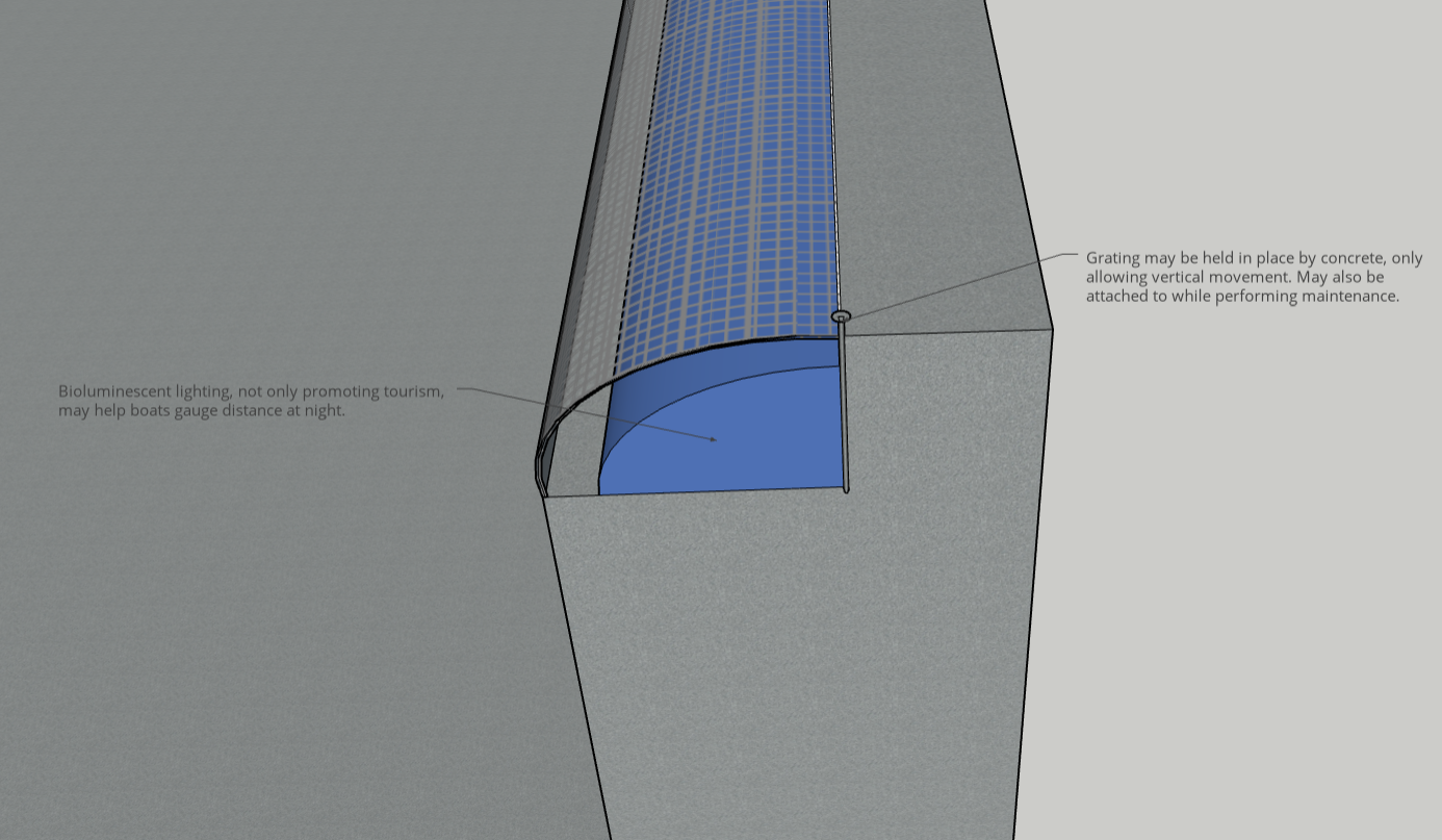
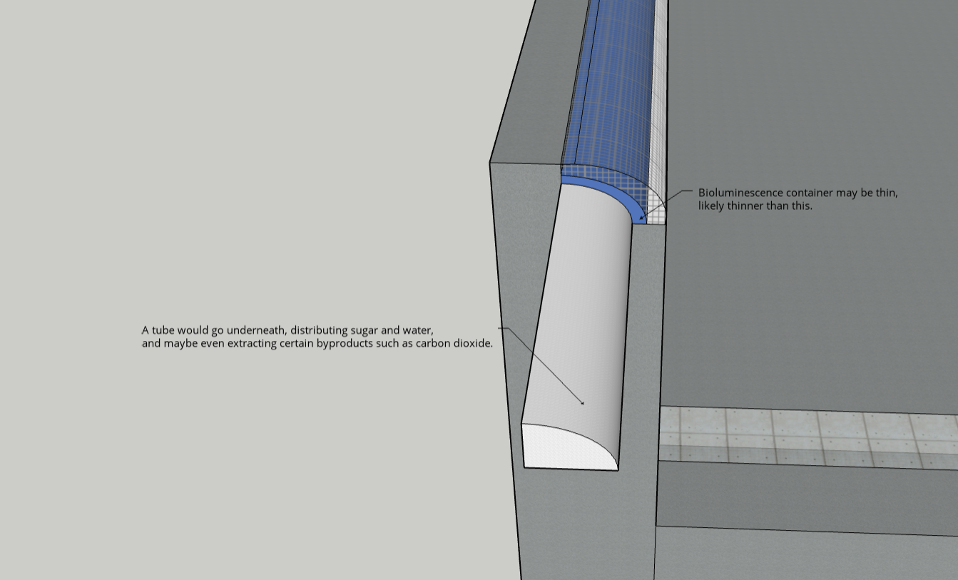
Having a background in computers and electronics, I explored the use of liquid crystals, such as those found in computer screens, to control the lights similar to that of above. Although it could be done, with a large margin for error I might add, I found the path not very worth exploring. This is because the filters used in liquid crystal displays often dim the light. Since the bioluminescent lighting is already dim on its own, I believe the result would be neither effective nor pleasant to look at. The following summarizes my findings: According to the University of Maryland 3b(University of Maryland), there are two different types of liquid crystals; those that change phases due to temperature or due to liquid density, called thermotropics and lyotropics respectively. In fact, lyotropic liquid crystals are often used in cells and organisms for various purposes. Within LCD (Liquid Crystal Display) screens, electricity is used to control the liquid crystals in a way that polarizes light. If you have two light polarizing films in the opposite directions, such as up and down vs left and right, little to no light passes through as light moves in waves and can't move in a direct route. When the two films are aligned, all light in a single orientation is permitted through. The problem with liquid crystals is that this means at least half of the light is lost through the filters similar to how sunglasses work. With bioluminescence being decently dim on its own, this could likely cause issues. Instead, I elected to look into some grating to protect the lighting while maintaining its visibility. This, of course, lacks any signalling capabilities but retains its attraction value. The whole system would look something as follows: The lighting container itself does not need to be thick. The container would likely be bevelled in some fashion. A thin cage could guard it which may be cut into smaller sections for ease of access. The guard would only be able to move vertically (via concrete balls or some other way to hold them). Using this concrete ball method also allows for worker safety if rope or harness is attached to act as a form of fall protection off the edge of the canal. As stated before, many forms of bioluminescent light need water, sugar, and oxygen. I feel this could all be fed through a tube underneath the bioluminescent layer (somewhat like a human vascular system). Another mimicry could be a similar method to that of oil and sweat excretion from pores. Because the bioluminescent process also produces byproducts, there may be a second tube that takes out carbon dioxide, TGA, and/or ammonia from the system to be stored or used elsewhere (Depending on how much excess is produced).
-
Underground Lighting
Underground lighting would be used for signaling on a basic level in order to help prevent collisions. These would come in a few forms; perpendicular lights shown below, parallel lights that may be used to indicate direction and speed, and diagonal lights to show entry or exit from certain locks and bridges.

-
Spanning Bioluminescent Lighting
Although providing less of a practical use, bioluminescent lighting may allow for tourism and a sense of wonder to flourish. Depending on the technology available, biproducts could be obtained and reused via methods mimicking biology.